GIANT SCALE RACING
GETTING STARTED AND AIRPLANE DESIGN
By Ed. E. Rankin
Introduction
The last article contained a step-by-step discussion of how to get started in Giant Scale Racing. This article will explore racing deeper. You have studied the USRA web site (www.usrainfo.org) thoroughly to understand what it’s all about, a wealth of information.
You have followed the instructions in the last article and
have joined the USRA; and have chosen a class and a model to race. The next
step is to understand what is important in the airplane design, construction,
and airplane systems setup. Then you need to understand Race Strategy.
What’s Important
I like this title that was suggested by Fred Sattler because it is so descriptive. Information will be given on what areas that really counts in the model design.
Your Model Selection
The following are some guidelines in the model selection process.
-
Scaling
Use the Common Rules and specifications from the USRA web site for sizing and determining model dimensions. Use the kit manufacture topic for airplanes available. Make sure that it follows these rules, so that you will not have to defend the kit design in the future. Use a USRA approved 3 view to check dimensions and wing areas.
The following is some simple equations to determine the scale factor and the resulting dimensions for the subject model.
Tsunami Full Size Airplane:
o Wing area = 146 sq. ft. = 21,024 sq. in.
o Length =28 ft. 6 in.= 342 in.
o Wing span = 27 ft. 6 in. = 330 in.
Scale factor for known model wing area:
From USRA specifications the known model wing area is: 1443 sq. in.
With this data the scale factor is determined by the following:
S.F. = (1443/21,024)½ = 0.262
Model Dimensions:
Wing Span, b = (330) (0.262) = 86.5 in.
Length, L = (342) (0.262) = 89.6 in.
To determine the dimensions of the model the USRA approved 3-view is scaled accurately. Be careful if you enlarge the 3-view because some processes don’t reproduce the same vertically and horizontally.
With the Tsunami example of b = 86.5 in. Determine the 3-view scale for model dimensions by measuring the 3-view wing span: b = 8.8 in.
3-view scale factor = 8.8 = 0.01073
86.5
Or 86.5 = 9.8295 (1 in. = 9.8295)
8.8
Subsequently, all 3-view dimensions can be scaled to 1 in. = 9.8295 in.
Useful geometric equations for airplane design are as follows:
Wing Area = [[(Root Chord) + (Tip Chord)]/2] x Wing Span
Sw = [(CR + CT)/2] x b
Wing Span = b
Root Chord @ Airplane Centerline = CR
Tip Chord = CT
Taper Ratio = λ = CT/CR
Aspect Ratio = AR = b2/sw = b/ [(CT + CR)/2]
If you want to design your own model from scratch, you can use the above equations to draw the model. Be sure you have a 3-view that is pre-approved by the USRA.
Draw the scaled dimensions on the 3-view and submit it to the USRA for approval before you commit to construction or for making a fiberglass mold for the fuselage, wing, etc.
If you want to design your model with a known span contained in the specs, use the following equations:
· USRA spec. span b model = ?
· USRA approved 3-view span, b threeview = ?
· Scale Factor, S.F. = bm /btv = ?
Use this scale factor ratio to scale all dimensions from the 3-view to draw the model.
-
Configuration details
A midwing configuration has lower interference drag than a low wing with the same wing area. It also requires no wing to fuselage fillet. However, it is harder to build and as a general rule is heavier than a low wing. A low wing configuration requires an expanding radius fillet. However, this type of airplane usually requires a removable fuselage frame for transportation.
A longer fuselage with the same fuselage cross section has a lower skin friction drag coefficient (C.f.e.) than a short one because the Reynolds Number is higher. Even though it may have more aerodynamic wetted area than the shorter fuselage with the same volume, it will have less total drag in pounds.
As a general rule, long tail fuselages are better configurations. Horizontal tails may be enlarged to produce more tail power and less elevator travel. This increased area moves the neutral point (N.P.) aft resulting in a higher static margin or allows the c.g. to the moved aft while maintaining the same static margin.
The Vertical Tail (V.T.) should be configured so that the rudder hinge linge is aft of the elevator trailing edge. This arrangement gives more rudder effectiveness. The V.T. should have a high aspect ratio to be as affective as possible in high angle of attack conditions.
-
Wing shape
Wings with AR= 6 to 10 have less drag-due-to-lift than ones with lower AR. However, the profile drag is higher. Profile drag is the sum of the wing skin fiction drag and the section lift drag. Also, the higher AR wings are heavier than low AR wings. This is because the bending moment at the root is higher with the same wing area. Weight is also higher to stiffen the wing to reduce deflection during high “g” turns. High aspect ratio wings are harder to transport.
When you compare all of the aerodynamic characteristics relating to AR, an AR= 6 is where the peak advantages occur.
High AR wings are difficult to land because the ground effect increases lift. An increase in lift occurs at a height of about 10% of the wingspan.
The wing taper ratio (λ) aerodynamic effects optimize at around λ=0.50.
-
Airfoil
There is a lot of attention paid to the selection of an airfoil, and some strange shapes result. Most of the non-dimensional data used for selection is 2-dimenisonal. 3-dimensional application should be considered which accounts for the installation on the airplane: Wing geometry (AR, λ, ө l.e.) and fuselage wing intersection effects. In addition, the airfoil must be analyzed for the Cl required for straight and level flight and the Cl required for pylon turns using the proper Reynolds Number. The selection is a big compromise. Don’t be fooled by airfoils that show low drag for a range of Cl (large drag bracket) but have poor pitching moment characteristics at high angle of attack and high Cl.
I recommend the NACA 63 or 64 series or Eppler series of airfoils of similar shape with t/c = 10-12% and with a 0.3 – 0.4 camber line. I have used this airfoil on pylon racing models for a long time and have found they give very good performance.
A very good article on airfoil selection can be found in the May/June 2002 RCX magazine. Therefore, I will not elaborate on airfoil theory. However, be aware that airfoils selection is not based on Clmax. They are based on about 0.80 – 0.90 Cl max that is required in pylon turns. The wing stalls at Cl max.
In general, the airfoil should have a medium size. L.E. radius, not sharpe, The T.E. should be slightly blunted (approximately 1/16 inch). Consideration must be given to assure Laminar flow from the stagnation point at the L.E. to as far back on the top surface before transition occurs to Turbulent flow. There are some people who like to use the phrase “Laminar Flow Airfoil Design.” This is just a jazz word to try to impress others. Actually all airfoils have Laminar flow up to the transition point to Turbulent flow. Even a flat plate has this characteristic. In general, the surface on the entire airplane should be as smooth as possible, especially on the wing at the L.E. to about the mid chord. This is to reduce the skin friction drag (C.f.e.) which is a major contributor to total drag in straight and level flight. This is shown in the following equations:
Drag=Protuberance Drag + Skin Friction Drag+ Drag due to lift
Drag = Protuberance Drag + C.f.e. (A wet/Sw) + (Cl) ²/πARe
High Cl is required in high ‘g’ pylon turns. Therefore, drag due to lift becomes a major part of the total airplane drag. During straight and level flight the drag-due-to-lift is low because of the low Cl required.
So, choose a good smooth airfoil without any cambered trailing edges. Airflow does not like to change directions, and when it does, flow separation and turbulence occurs producing unwanted drag.
-
Horizontal and Vertical Tails
The horizontal tail (H.T.) should be located in an area where it is always in the wing downwash or in an area out of the downwash at all times to be effective. For a midwing configuration the H.T. should be located in the same plane as the wing chord plane. For a low wing airplane the H.T. should be located no higher than 25-30% of the wing root chord plane. “T-Tails are located completely out of the wing downwash, but they give “pitch-up” without stall warning at high angles of attack. They are not recommended for pylon racers that pull very high “g’s” and angle of attack on pylon turns. Sometimes they will snap roll and crash.
Weight and Balance
It is very important to build your race model to the spec. minimum weight and be structurally sound. In addition, maintaining the proper balance point is very necessary to assure good handling qualities with high maneuverability. Building a light airplane with the proper center of gravity and with the proper control surface travels with result in a fast model with the best turn rate at the pylons that is possible with the selected configurations.
-
Weight Maintenance
You should establish a bogey weight for each component, subassembly, and fixed aircraft systems. Divide this task into two categories: finished airplane, and the required fixed equipment weight.
Using the Proud Bird F-1 as an example:
Minimum Dry Weight = 25lbs.
Fixed Equipment
Engine/Exhausts Stacks
Prop/Spinner
Fuel System (Tanks, Tubing, Mix. Control,
Fuel Line, “T” Fitting, Pressure
Dump Valves)
Radio (Battery, Receiver, Foam Wrapping, Servos,
“Y” Harness, servo extensions switches. Etc.)
Push Rods
Landing Gear,
Wheel Pants, Wheels
Total = 9.5 Pounds
Subtracting 9.5 pounds from 25 pounds gives 15.5 pounds allotted for the finished model ready to fly without equipment. Allow 2 pounds for finishing (painting fuselage, monocoating wings and horizontal tail) which gives 13.5 pounds bogy weight for the model without the finishing coats. The total model ready to paint without equipment should then weigh 23 pounds.
Weight Bogy
Summary
Fixed equipment = 9.5 pounds
Total airplane w/o finish = 13.5 pounds
Finish= 2 pounds
Total Airplane Ready to Fly = 25 pounds
I will
discuss some tips later on how you can reduce structural weight. To keep the structural weight low, it is not
the big things you do, but a whole lot of little things. My prototype Proud Bird weighs 25 pounds 10
ounces with a larger horizontal that is not needed. Two ARF models built by myself and Jerry Bradley weigh 23 pounds
ready to fly with all equipment and no paint.
Charlie Powell’s model weighed 23 pounds ready to fly and he had to add
2 pounds of weight to bring it up to the minimum of 25 pounds. Other Proud Birds being built are achieving
the same weights. This is proof that
the minimum weight can be achieved by following these procedures and the useful
building tips to save weight. Remember
you can’t take weight off after the model is finished.
-
Center of Gravity (C.G.) Control
Achieving the proper c.g. on a race model is another major and important factor in producing a good racing airplane. For most models the c.g. should be located at 20-25 % of the mean average chord (MAC). This depends on the resulting pitch stability derivative, and the type of handling qualities best suited to the pilot. I will discuss the pitch/ yaw/ lateral derivatives later.
The c.g. of the complete airplane with the landing gears and engine prop/spinner should be checked as you are building so that the desired c.g. can be achieved.
The following formulas are shown to calculate the mean average chord (M.A.C.) and its location on the wing so that the c.g. location can be determined:
M.A.C. = ĉ = ⅔CR [(1+ λ)-(λ / (1+ λ))]
ŷ = b/6[1+ (2 λ)]/ (1+ λ)/ (1+ λ)
x = (Tan Өl.e.) b/2
m= (TAN Ө l.e.) ŷ
c.g. LOCATION = m + 0.20c
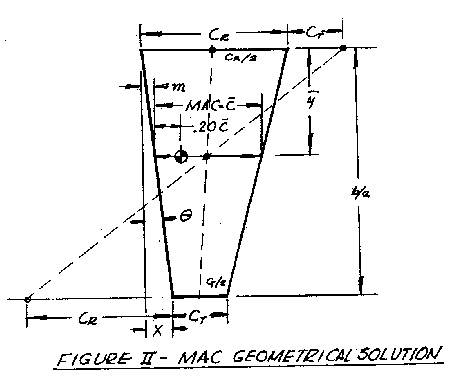
The following drawing in Figure 1 is shown to illustrate these parameters. A graphic solution to determine the wing M.A.C. is shown in Figure 2.
FIGURE 1: Wing Geometry
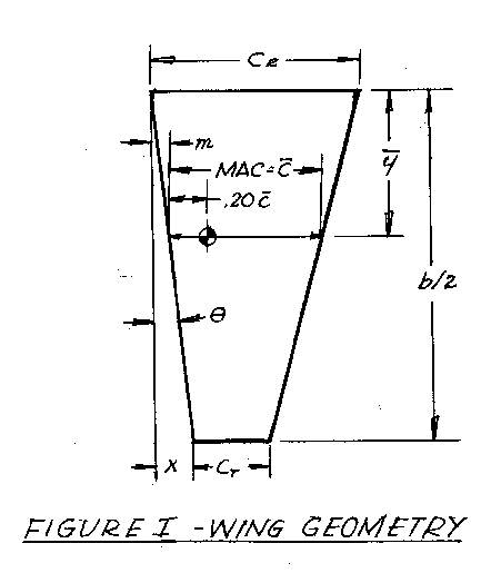
FIGURE 2: MAC Geometric Solution
-
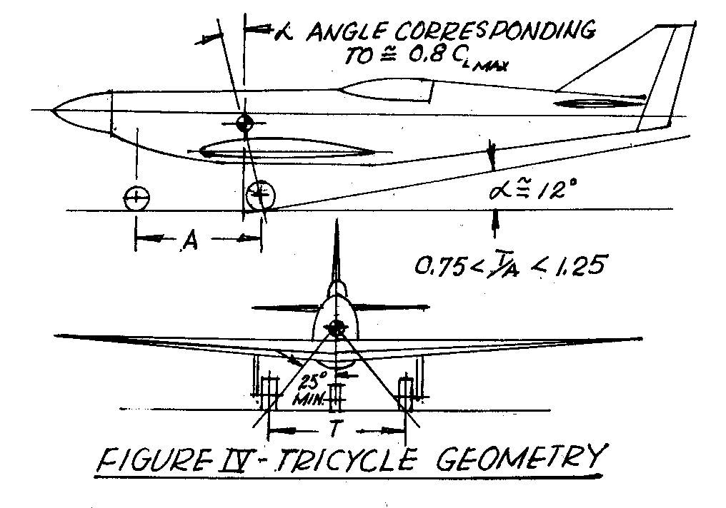
Landing Gear / C.G. relationship
To achieve good takeoff and landing characteristics the relationship of the centerline of the wheel and the c.g. must have the geometric characteristics shown in Figure 3.
FIGURE 3: Conventional Landing Gear
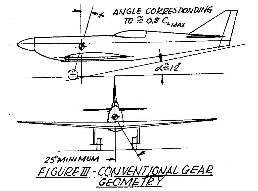
FIGURE 4: Tricycle Landing Gear
Airplane Stability
Static stability is defined as the ability of the airplane to return to normal straight and level flight without control inputs after a gust upset.
The pitch, lateral, and directional stability of an airplane is very complicated and is interactive. It depends on the mass moment of inertia of the airplane in all three axis; the aerodynamic flow effects of the fuselage and its shape on the vertical and the horizontal tail; the aerodynamic flow (down wash) effects of the wing on the horizontal tail which is highly dependant on their geometric relationship; and the geometry of the fuselage, wing, horizontal and vertical trail. This is in addition to the location of the thrust line.
-
Pitch Stability
The aerodynamic loads from the wing vertical lift load and pitching moment and the C.G. location (weight) are balanced with the down or up load of the horizontal tail. From this, the aerodynamic center (neutral point) can be determined.
The distance from the a.c. to the c.g. is expressed in a ratio of d/ĉ.
This is the longitudinal static stability and is normally about 0.15 ĉ, giving the neutral point location at about 35-40% ĉ.
The pitch stability derivative is as follows:
= (dє/dα) x (Horizontal tail volume coefficient)
The first term is an expression for the wing downwash effects on the horizontal tail. This can be calculated but requires verification from wind tunnel tests. There are acceptable values for the horizontal and vertical tail coefficient for the full size airplanes which apply to model airplanes regardless of size. Scaling effects has no impact on the required coefficient values except for mass moment of inertia.
The following equation is shown for the horizontal and vertical tail volume coefficient:
Horizontal tail vol. coef. = (tail length/ wing MAC) x (horiz. Tail area/wing area)
T.V. (h.t.) = (l/ĉ) x (S.v.t. /Sw)
Tail length =distance from ĉ/4 of the horizontal tail to the ĉ of the wing.
Acceptable values for T.V. (h.t.) = 0.30 to 0.40
-
Directional Stability
Vertical Tail Vol. Coef. = (Tail Length / Wing span) x (Vertical Tail area/ wing area)
T.V. (v.t.) = (l/b) x (S.v.t/Sw)
Acceptable
values for T.V. (v.t.) =0.03 to 0.05.
Notice that the span of the wing is in this equation instead of the
MAC. This is because the vertical tail
interacts with the wing geometric characteristics and resultant aerodynamic
characteristics for directional stability.
-
Lateral Stability
Again this requires long and lengthy calculations which are not appropriate in this article. There are several good general rules to follow that are helpful in fall size airplanes and model airplanes.
√Mid-wing airplanes require no dihedral.
√Low wing airplanes with zero sweeps at 25% or 35% chord line require a minimum of 3 degrees dihedral. If the coef. (v.t.) is low they may require 4 degrees of dihedral.
√Low wing airplanes with a leading edge sweep of 15 degrees or more and a straight trailing edge requires no dihedral. This is because of the inherent lateral stability effects of a swept wing.
Control surface size and travel
-
Ailerons and Flaperons
For conventional ailerons the hinge line is usually located at about the 80% wing chord line with the inboard edge at the 60 to 70% half span and continue to the wing tip. This will depend on the AR of the wing.
For flaperons the surface hinge line is usually located at about the 80 to 90% chord, and covers the full length at the trailing edge from the root to the tip.
Differential control surface travel is required for both conventional ailerons and flaperons to counteract adverse yaw when deflected. For both types of surfaces approximately (+) 15 degrees up and (-) 10 degrees down is a good place to start. Flaperons should have approximately 3 degrees of down travel when programmed with up elevator command.
Contrary to some modelers belief the horizontal and vertical tail size doesn’t have to be increased for a scaled model airplane. If the full size airplane is statically stable the model should also be stable with a proper c.g. location at approximately 20 to 25% ĉ c.g.
-
Elevator and Rudder
The elevator hinge line is usually located at 70-80% chord line. Travel depends on the pitch static margin but as general rule (+) 15 to (-) 10 degrees is acceptable.
The rudder
hinge line is normally located at the 70-80% chord live. Travel should be (+) or (–) 30 degrees for
very positive directional control at takeoff and landing.
Model Construction
There is a saying: “You can’t
remove weight from the structure after it’s built.” Therefore, you must control the weight while under construction
with good building techniques. The
structural efficiency is higher when the weight is reduced for the same
strength. In general, this is what you
should try to achieve in building your model.
Don’t’ leave out structure to save weight; it is there for a purpose. Lower weight gives lower wing loading and
faster pylon turns.
-
Air Loads
The “g” forces for a pylon racer are very high compared to a full size airplane. Our race models produce 25 to 26 “g” forces in the pylon turn. Full size airplanes are designed for about 10 g’s. However, pylon turns for full size airplanes are limited to the pilot’s physical compatibility without “g” suits. Examples of some of the model loads that are produced are as follows:
Unlimited class @ 40lbs
Resultant wings load =26x40 =800lbs
Formula-I class @ 25lbs
Resultant wing load = 26x25=650lbs
So you can see why it is important to build as light and as strong as possible to reduce airloads and within the USRA class Specs.
-
Building the Model
-Fuselage
When buying a fiber glass kit, be sure that the fuselage is as light as possible. It doesn’t have to be heavy to be strong. Usually, the shell should be very light with no gel coat (this is heavy and not necessary). It can then be reinforced with light ply frames with ⅜ inch rim dimension. Drill lightening holes in the shear webs where it is feasible. Especially, drill lightening holes in 5-ply members such as cross-members for the wing tie-down structure. Use slow drying epoxy mixed with cabosil or microballons to install all frames. Apply a very thin coat and don’t wipe-in a fillet because it is not necessary.
-Wing and Tails
Glue understructure with Titebond because it is lighter than epoxy. Use Titebond to glue leading/trailing edges and tips. Never use contact cement of any kind to glue the wing skins, it is not strong enough for giant scale race models. Use Elmer’s ProBond for attaching the wings skin. It is a polyurethane expandable adhesive and is strong and lighter than epoxy resin for skin attachment. Use AAA 8 pound density balsawood for the skis and all the structure.
-Joints
When constructing any of the components take the time required to make all joints fit very accurately. This will minimize the glue weight required for the joint and will minimize the requirement for filler. When filler is used be sure it is very light weight with microballons.
-
Finishing
-Fuselage
The first step in finishing the fuselage is to fill the pin-holes, seams, and voids. Do this with lightweight Bondo and sand. Then brush coat with a mixture of primer and cornstarch. It looks terrible when dried but sand it all down to the fiberglass. Next spray several coats of primer, sanding between each coat using 400 wet sandpaper for the final sanding. It should look shiny when finished and ready for the paint. You can paint with either a base coat/clear coat or a single stage acrylic urethane system. If you have a lot of different colors and striping, the base coat/clear coat system is the best but is heavier than the single stage system. I prefer the single stage system because it is lighter. However, it is harder to apply but still looks good with a shiny finish.
-Wings and Tails
If you choose to paint the wing and tails, cover them with 0.50 ounce fiberglass cloth using epoxy resin thinned with alcohol. Use an applicator to squeegee it to the surface. It should have a dry look when finished. Ration the epoxy used because it is heavy. Brush a coat of primer on the surface and sand it down to the fiberglass. Spray several coats of primer sanding in between coats. Finish sanding with 400 wet sandpaper and paint as described for the fuselage.
You can save about one pound if you monocoat the wings and tails, but it is not as durable as a paint job. However, it is easier to patch. I use monocoat for the wings and tails on my F-I because they are so large. My first two Polen Special Experimental class airplanes had a wood fuselage and the entire airplane was monocoated. It held up real well at 230 mph.
-
Aerodynamics Details
-Holes, gaps, protuberances
It is very important to minimize the access holes; gaps in removable mating surfaces; and protuberances. These all cause drag. However, holes are necessary for servicing the airplane such as for the glow plug drivers. This can be avoided by using a remote glow driver system. Be careful these systems sometimes fail on the starting line resulting in zero points. Some holes are necessary for fuel servicing. Minimize these holes, but remember to make them “user friendly.”
All gaps that occur at the intersection of removable components should be taped prior to flight.
Minimize protuberances such as switches, fuel servicing plugs, and landing gear air fill fittings. Sometimes, these can be placed in compartments inside the fuselage with a spring loaded hatch.
-Fillets
Fillets are desired for the horizontal and vertical tail and wing to reduce the interference drag.
Midwing configuration requires no large fillet. However, low-wing configurations require a large fillet to reduce large interference drag. An expanding radius fillet from the L.E. to the T.E. is required with a smooth transition between the T.E. and the side of the fuselage. The Tsunami is an example of a good wing fairing design. Notice the T.E. transition and its planform shape.
-
Aircraft System
-Control System
All pushrods should be as short as possible and carbon composite tubes should be used. For long pushrods, several supports (fairleads) should be used to prevent deflection. You should not have any slop at the servo connections or no deflections under loading conditions, 6-32 clevis assemblies should be used at all pushrod ends with a safety clip.
Servo mounts should be structurally sound. Servo mounting screws should be locktited.
Control surface hinge lines should have minimum gaps for lower drag and reducing flutter. You should have no binding thru-out the surface travel.
Rocket City control horns or equivalent are recommended. Large Robart hinges should be installed every 3 inches (lots of hinges).
-Radio Installation
It is very important that metal gear servos complying with the USRA rules be used on all primary control surface. Plastic gears will not withstand the vibration at the high speeds giant Scale racers are attaining. Torque ratings are only the steady state holding power. Small servos even with metal gears and high torque ratings are not adequate. Lots of gear teeth are required to take the high vibration. Standard serves with plastic gears can be used for all other functions.
The receiver and battery should be wrapped with foam rubber and either secured firmly in a box or with Velcro.
-Fuel System
I recommend Fred French’s fuel system design with a header tank and main fuel tank, mixture control and fuel pressure dump. This system works well when using injectors with a slider valve. Also, it works well with carburetors.
Size your tanks for at least 6 to 10 minutes of running time, because sometimes there is a delay in the starting while you are in the air. This is a trade between added fuel weight and being safe or having minimum fuel quantity and taking the chance of running out of fuel and receiving a zero.
Use a good grade of fuel tubing with a size compatible with your engine to have adequate fuel flow. Be sure there are no kinks or loops in the fuel line.
Have a way to pinch off the fuel line to the carburetor during fueling to prevent flooding. Cut plenty of drain holes in the bottom of your cowl for fuel drainage to prevent possible fires.
Wrap the fuel tanks with foam rubber and secure to fuselage structure with 2 inch Velcro.
Tie-wrap all fuel tubing joints at the tank, fuel tees, mixture control and engine. Use a high quality check valve for the crankcase pressure line.
-Engine /Spinner/Propeller
Mount the engine for easy installation and removal. Be sure that the mounting bolts are accessible. Use glow plugs that will not leak under pressure. Use Permitex High Temperature thread lock on the glow plug and the plug adapter to prevent leaks.
Pin the spinner rim to the back plate. On large engines (2) to (4) ¼– 20 Allen head bolts should be attached thru the propeller washer, prop, spinner, and to the prop hub to prevent slippage/damage. Use locktite on these bolts and safety wire the heads. Balance the spinner and prop to prevent vibration.
Choose a prop to match your engine and airplane. Ask experience pilots what you should use, they will help you. We have a good group of people in our organization who are more than willing to help, just ask! Carbou fiber props are recommended and are available from Supercool, Aerosport, and Zinger. Go to the USRA website for this information.
For enclosed engines build baffling cooling system designed for proper flow in and around the engine. This is important! The exit should be on the bottom of the cowling even though this is a positive pressure area. This exhaust cooling air flow exit will not interfere with the critical airflow around the fuselage. I’m working with Dan Boud, Engineer on the Nemesis. Hopefully, I can develop some good engineering design guidelines.
-Safety Check
Go to the
USRA website and get a copy of the safety check requirements. Perform these tasks on you airplane prior to
test flying, and prior to entering a race contest.
Race Strategy
Preparation
-Engine run-up, engine/fuel system tuning
√Engine ground RPM to standard
√Mix control programmed with throttle/injection system with sliders
√Engine shutoff/pressure dump operation
√Radio range check with full engine throttle (range/no servo glitches)
-Flight Testing
-Set surface trims for straight and level flight
-Set travels for 90° full elevator travel turns
-Practice landing pattern approach and touch down (usually wheel landing is safer/ let go elevator stick as soon as wheels touch)
-Check RPM/EGT/CHT with data logger.
For twins check CHT for equal 275°F. EGT for 750°F
-Equipment- Prepare and maintain
√Fire Extinguisher!!!!
√Starter/battery- working order and charged
√Glo drivers- good batteries with fresh charge
√Starting cart or wagon to transport equipment to flight line
√Extra glo plugs/ tools
√Fuel dispersing system-fresh batt- electric pump operation
√For the pit- tool box with all required tools to service airplane, extra props fuel, motor tool, drill motor drills, extra props/spinners, spare engines/parts, tent/chairs
√Starting line team
-Pilot/caller/holder/starter
-Organize duties –caller synchronizes with pilot (no cuts)
-
The Race-(study the USRA race procedure guide)
If you are a beginner you are unlikely to win in you first few races. However, if you follow these instructions there is a possibility that you may end up in the Gold race and could place high. Sometimes, the fastest airplane and best pilots don’t win. This has happened many times because the fast guys may cut a pylon, jump the start or have a mid air collision. Remember there are a minimum of five heat races and most of the time six heat races to accumulate points for the Gold and Silver races. So, each heat race is very important.
√Get your engine started and your airplane launched on time. Use the warm-up laps to adjust to the course, observe the dead line. Have your caller get in rhythm with your style of flying and get adjusted to the pylon course to call quick pylon turns. Fine tune mix control.
√Get a good start on the starting clock. There is usually an audio countdown to help you position the airplane for a good start. If you can’t judge the airplane speed/start coordination, just stay with the lead airplane.
√Avoid mid-air collisions. Remember there are four other airplanes on the course just as anxious to win as you are. The best thing to do is to fly higher than the fast guys and don’t try to mix it up with them. If you do you are likely to get in trouble. Also, be very careful on landing to avoid ground collisions. Land long or short or any way you can to avoid hitting airplanes that have already landed. In addition, avoid runway landing lights, they tear up airplanes. Your caller plays a very important role in helping you to land.
√Learn not to cut pylons, the time penalty will place you last in a heat race except when everyone else cuts. Coordinate with your caller on commands to “get ready” and “turn”. Pilots don’t anticipate his command, because the caller gives this command before the pylon light is turned on so that you can fly a tight course.
√Fly a
wide course when flying solo in a heat; all other airplanes have a cut or have
a zero; the other airplanes are much faster; or you will place last in the heat
regardless if you fly a tight course or not.
Save your airplane.
Scale Speed
Have you ever wondered about the scale speed of our giant scale racers? The following is an example:
· P-51, V=550 MPH@ Sea Level
Scale speed for 22.5% Model= (0.225)½ 550=260 MPH
· Nemesis, V=270 MPH@ Sea Level
Scale speed for 42% Model= (0.42)
½ 270= 174.98 MPH
In Closing
Remember, your log books must be signed-off by authorized USRA designators: District representatives or the USRA Technical Advisor. You must supply a USRA approval 3-view with model dimensions. Don’t wait until race time. I have a comprehensive file on 3-views of all racing models. Copies are available at your request.
In my next article I will give you more information about our race model’s dynamically similar values compared to full size airplanes. In addition, propeller design will be discussed: how to calculate geometric pitch and how to determine model maximum speed.
Maybe I will have an article on engine tuning and engine cooling inside a cowling.
Give me your comments and what you would like to see in these articles.
Phone: (817)-292-0465 E-mail: rankined@sbcglobal.net